
內核驅動結構(Part II)
Structure of Linux Kernel Device Driver
ref. https://www.youtube.com/watch?v=XoYkHUnmpQo&list=LL&index=1&t=272s
Talk to the hardware
在操作系統中有幾種機制能夠讓CPU與硬件設備進行通信:
- Port I/O: 使用一個專用的總線進行用心
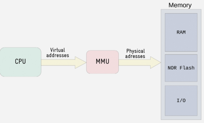
- Memory-mapped I/O: 與硬件設備共享內存地址空間進行通信,(have the I/O devices mapped to our address spaces, so in the address space you have the registers there where you can talk to the hardware ),這種方法更為常見
在Memory-Mapped I/O(MMIO)機制中,將I/O設備映射到內存地址空間,然后CPU可以通過寄存器與硬件進行通信,所以當用戶使用指針向某個地址寫入數據,實際上是將數據寫入了寄存器中。
使用mmio與硬件設備進行通信的三個步驟:
- 向MMIO寄存器發送請求,通過一些內核API完成,比如request_mem_region(), it's recommended, not mandatory
- 將寄存器的物理地址映射到虛擬地址,比如使用函數ioremap()
- 使用內核API讀寫寄存器,比如readb()\writeb(), readw()\writew(), readl()\writel(), readq()\writeq(),分別進行8-bit, 16-bit, 32-bit以及64-bit的讀寫
當然也可以使用函數ioremap()返回的指針進行讀寫,不過推薦使用內核封裝的函數對這個指針進行操作,注意使用iounmap()釋放掉這些地址空間。完成地址映射后,可以通過cat \proc\iomem來查看I/O設備的地址映射。
下面這段代碼用于控制一個LED燈設備的驅動:
#define GPIO1_BASE	0x0209C000
#define GPIO1_SIZE	8
#define LED_OFF	0
#define LED_ON	1

static struct {
	dev_t devnum;
	struct cdev cdev;
	void __iomem *regbase;
    // device datas area
} drvled_data;

static void drvled_setled(unsigned int status)
{
	u32 val;

	/* set value */
	val = readl(drvled_data.regbase);
	if (status == LED_ON)
		val |= GPIO_BIT;
	else if (status == LED_OFF)
		val &= ~GPIO_BIT;
	writel(val, drvled_data.regbase);

	/* update status */
	drvled_data.led_status = status;
}

static ssize_t my_write(struct file *file, const char __user *buf,
			    size_t count, loff_t *ppos)
{
	char kbuf = 0;
	if (copy_from_user(&kbuf, buf, 1))
		return -EFAULT;

	if (kbuf == '1') {
		drvled_setled(LED_ON);
		pr_info("LED ON!\n");
	} else if (kbuf == '0') {
		drvled_setled(LED_OFF);
		pr_info("LED OFF!\n");
	}
	return count;
}

static const struct file_operations drvled_fops = {
	.owner = THIS_MODULE,
	.write = my_write,
};

static int __init init_module(void)
{

	if (!request_mem_region(GPIO1_BASE, GPIO1_SIZE, "my_device_driver")) {
		// handle error
	}

	drvled_data.regbase = ioremap(GPIO1_BASE, GPIO1_SIZE);
	if (!drvled_data.regbase) {
		// handle error
	}

    // Device driver initialization and installation

    return 0;
}

static int __exit exit_module(void)
{
    iounmap(drvled_data.regbase);
	release_mem_region(GPIO1_BASE, GPIO1_SIZE);
    // Unloading and unregistering the device driver
}
通過上面的這些API,可以通過讀寫對應了設備文件控制對應的硬件設備。下圖是一個LED的驅動,其整體框架如下:
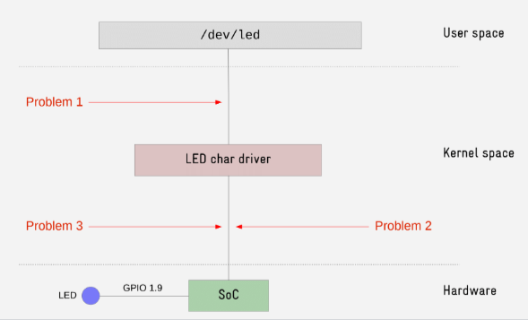
這樣的框架存在一些問題:
- 用戶訪問設備文件所使用的接口是自定義的,而沒有進行標準化
- 從GPIO控制器中為設備驅動分配了兩個寄存器,那么其他GPIO將無法訪問這兩個寄存器,
假設GPIO控制器中有32個GPIO,那么沒有人能夠使用其余的另外31個GPIO - 在設備驅動中采用硬編碼的方式寫入硬件相關的信息,那么如果修改了硬件,也必須修改驅動
因此,這樣的框架還需要一定程度的解耦合并進行模塊化。
Driver Model
Linux驅動模型提供了多個設備驅動抽象(abstraction to device drivers),這能夠使驅動代碼更模塊化、可重用并且容易維護。
該驅動模型的組成如下:
- Framework:根據設備類型導出的標準化接口
- Buses:從設備驅動中抽象出來的設備信息以及設備所連接的位置
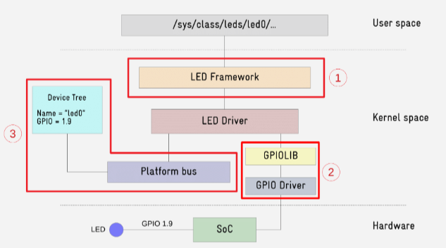
使用驅動框架(linux/leds.h for led device)將接口標準化后,意味著驅動開發者不再需要定義file_operations來指定回調函數的行為,這些接口以及對應回調函數都由對應的框架完成定義。Users know beforehand the interface provided by a driver based on its class or type.
為了避免硬件資源被一個設備獨占,需要使用特定的API進行動態控制,比如對于LED設備,Linux內核中實現了一種生產者/消費者的模型(gpiolib)來管理GPIO資源。
- GPIO producer,類似于GPIO控制器的驅動
- GPIO consumer,類似于LED設備的驅動
如下,使用了框架將用戶接口標準化,并使用內核接口管理硬件資源:
#include <linux/leds.h>
// other header files

struct drvled_data_st {
	struct gpio_desc *desc;         // change from "void __iomem *regbase;"
	struct led_classdev led_cdev;   // change from "cdev"
};

static struct drvled_data_st *drvled_data;

static void drvled_setled(unsigned int status)
{
    // not use the writel()
	if (status == LED_ON)
		gpiod_set_value(drvled_data->desc, 1);
	else
		gpiod_set_value(drvled_data->desc, 0);
}

static void drvled_change_state(struct led_classdev *led_cdev,
				enum led_brightness brightness)
{
	if (brightness)
		drvled_setled(LED_ON);
	else
		drvled_setled(LED_OFF);
}

static int __init drvled_init(void)
{
	int result = 0;

    // no need for driver initialization
    // no need for iommp for device

	drvled_data = kzalloc(sizeof(*drvled_data), GFP_KERNEL);
	if (!drvled_data) {
		// handle error
	}

	result = gpio_request(GPIO_NUM, DRIVER_NAME);
	if (result) {
		// handle error
	}

	drvled_data->desc = gpio_to_desc(GPIO_NUM);

	drvled_data->led_cdev.name = "ipe:red:user";
	drvled_data->led_cdev.brightness_set = drvled_change_state;

	result = led_classdev_register(NULL, &drvled_data->led_cdev);
	if (result) {
		// handle error
	}
    // ...
}

static void __exit drvled_exit(void)
{
	led_classdev_unregister(&drvled_data->led_cdev);
    // not use the iounmap()
    gpio_free(GPIO_NUM);
	release_mem_region(GPIO1_BASE, GPIO1_SIZE);
	kfree(drvled_data);
}
// ...
使用設備框架對驅動進行重組后,用戶不再直接與/dev/目錄下的設備文件進行交互,而是在目錄/sys/class/led目錄下找到所有的LED類的設備,進入所注冊的驅動目錄下,可以找到控制LED設備的接口,這些接口仍然以文件的形式存在,但是和之前所定義的接口相比會更加標準化,也就是幾乎所有的LED設備都可以使用這樣的接口進行控制。
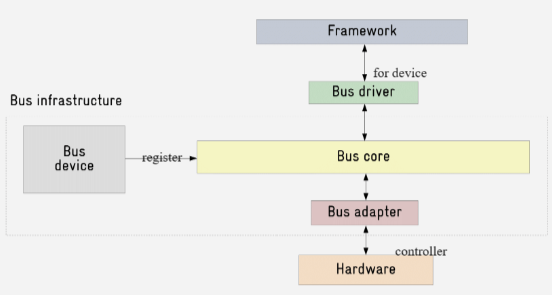
Bus infrastructure
最后,可以使用總線框架實現設備與驅動的解耦合。總線框架組成如下:
- Bus Core: 對于給定總線類型(USB core, PCI core, etc)所實現的API, (represented in the kernel by the "bus_type" structure)
- Bus adapters:總線控制器驅動, (represented in the kernel by the "device_driver" structure)
- Bus drivers: 負責管理連接到總線的設備, (represented in the kernel by the "device_driver" structure)
- Bus devices: 所有連接到總線的設備, (represented in the kernel by the structure "device")
總線框架如下圖所示:
解耦合的實現:在總線框架中,驅動相當于是一種類(class),當用戶在總線上注冊設備時,將會產生這個類的實例。以I2C總線設備為例,下圖演示了這個過程:
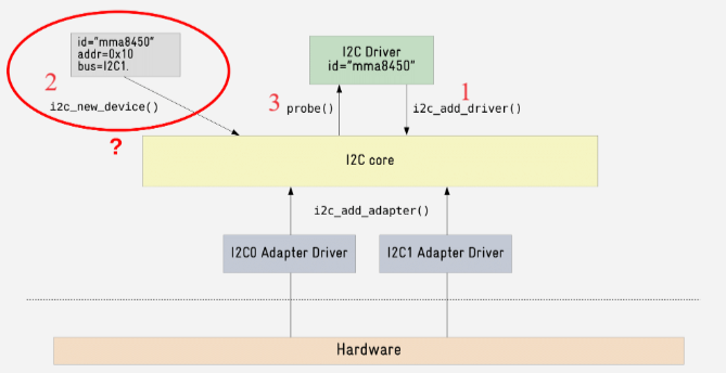
這個過程可以大致分為三步:
- 在Bus Core注冊驅動
- 在Bus Core注冊設備,隨后Bus Core將會匹配對應的驅動
- 匹配成功后,Bus Core將會通過probe()函數調用驅動對應的回調函數,進行實例化
有很多種方法向總線注冊一個設備:
- 使用Bus Core提供的接口,在用戶應用中靜態注冊一個設備,比如I2C Bus提供的
i2c_register_board_info(),或者虛擬總線Platform Bus提供的platform_device_register() - 使用硬件平臺提供的注冊機制,比如X86提供的ACPI
- 使用設備樹,比如PowerPC以及ARM提供的標準化機制
- 有一些總線支持通過設備枚舉(device enumeration)來自動添加設備,比如PCI總線的
lspci命令
 浙公網安備 33010602011771號